
Locate the Cavity
Confirm the intended position against vanity, faucet, lighting and adjacent doors or walls.
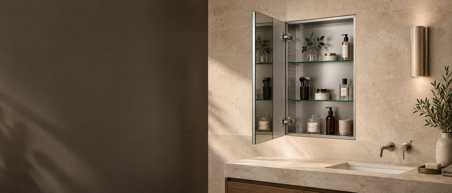
Coordinate the visible mirror with the hidden cabinet body, rough opening, wall cavity, door movement and electrical route—before production begins.
A recessed medicine cabinet places the cabinet body inside the wall so the mirrored face reads as a clean, integrated element. That appearance depends on more than overall width and height.
Wall build-up, usable cavity depth, studs, plumbing, wiring, flange coverage and door clearance must be aligned with the cabinet construction. OJMIRROR turns these inputs into a reviewable project direction.
Final dimensions, tolerances, construction and functions require drawing, sample and order review.
Nominal product size alone is not enough. The visible face, cabinet body, rough opening and available wall cavity are related—but they are not interchangeable dimensions.
The wall can eliminate an installation direction before appearance, storage or electrical features are selected.
Confirm the intended position against vanity, faucet, lighting and adjacent doors or walls.
Measure usable cavity depth after the finished wall, tile and internal obstructions are considered.
Identify studs, blocking, plumbing, wiring, insulation or other constraints before defining the opening.
For lighted or powered cabinets, coordinate cable entry, component position and future service access.
Installation feasibility and structural/electrical work should be confirmed by the responsible local project professionals. OJMIRROR reviews the cabinet against the information supplied.
A listing such as 24 × 30 in usually describes the visible or nominal product size. It does not automatically tell the installer the cabinet-body dimensions or the opening to cut.
For replacement work, measure the existing opening at the top, center and bottom, then record the smallest clear dimension. For new construction, coordinate the opening from the selected cabinet drawing before wall closure.
| Dimension | What it controls | What to send |
|---|---|---|
| Overall W × H | Visible scale above the vanity and relationship to lighting, faucets and side walls. | Target face size or room elevation. |
| Cabinet-body W × H | The portion that must enter the wall cavity. | Selected drawing or existing box size. |
| Body depth | Internal storage and the minimum usable cavity behind the finished wall. | Requested depth and available cavity. |
| Rough opening | Cutout, installation clearance, shimming and access to fixing points. | Measured opening or drawing-defined requirement. |
| Flange / overlap | Coverage of the cut edge, tile transition and finished perimeter. | Wall finish and desired visible trim. |
| Door clearance | Hinge handing, opening angle and interference with walls or lights. | Plan/elevation and nearby obstacles. |
Common search sizes such as 16 × 20, 16 × 24, 20 × 30, 24 × 30, 24 × 36 and 36 × 30 are useful starting references—not confirmed OJMIRROR stock specifications.
The mirror face is the visible result. The cabinet body, wall opening and available cavity determine whether the recessed installation will actually fit.
Compare by door layout, visible size and function. These are inquiry directions—not stocked SKUs. Final cabinet-body size, rough opening, depth and electrical scope follow the reviewed drawing.
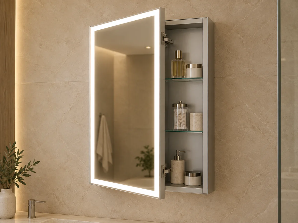
A compact flush storage direction for single-vanity and narrow-wall layouts.
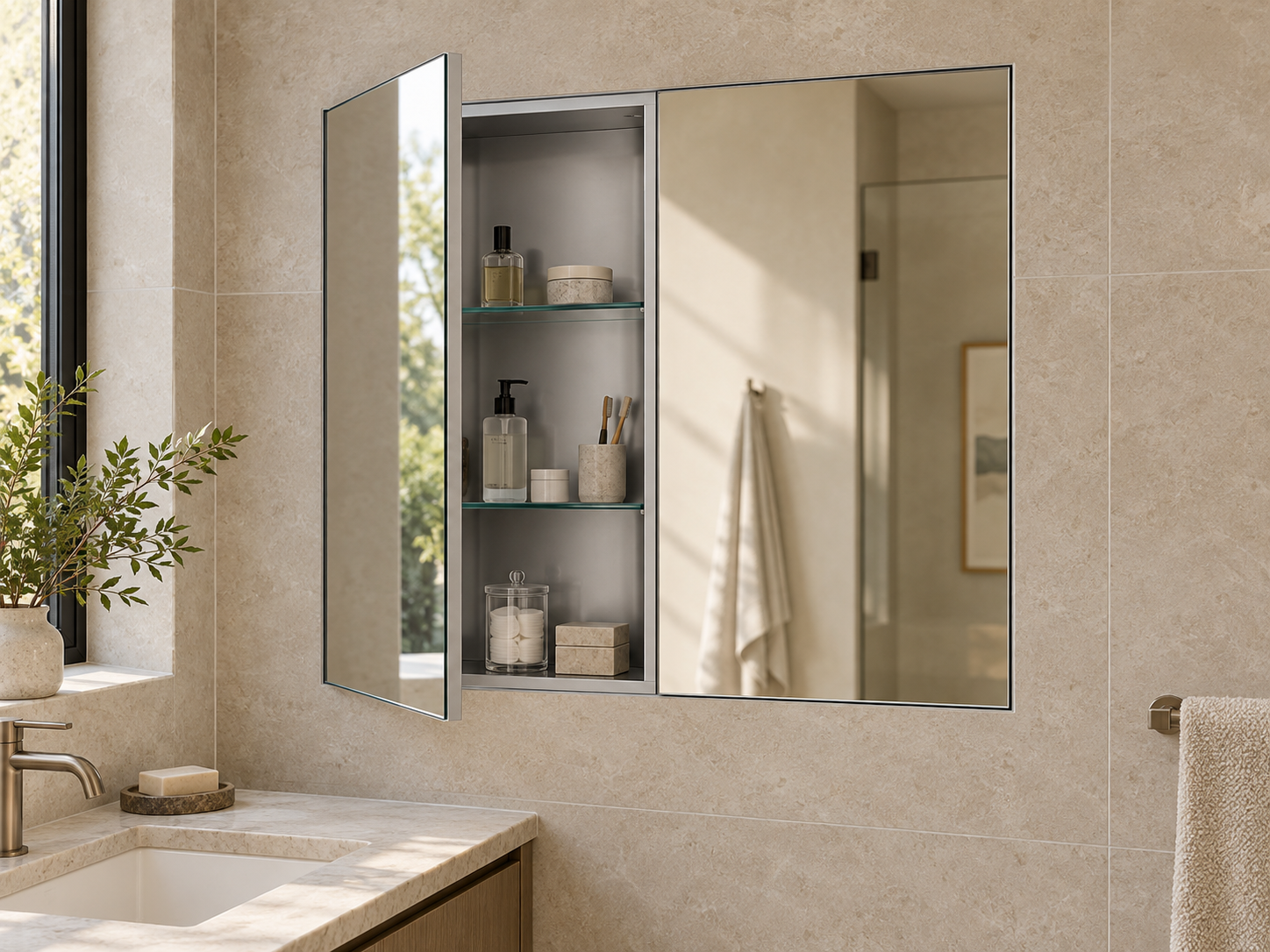
A wider mirrored face with divided access and coordinated hinge movement.
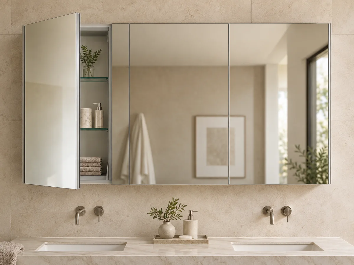
A wide storage direction for larger vanities and repeated access zones.
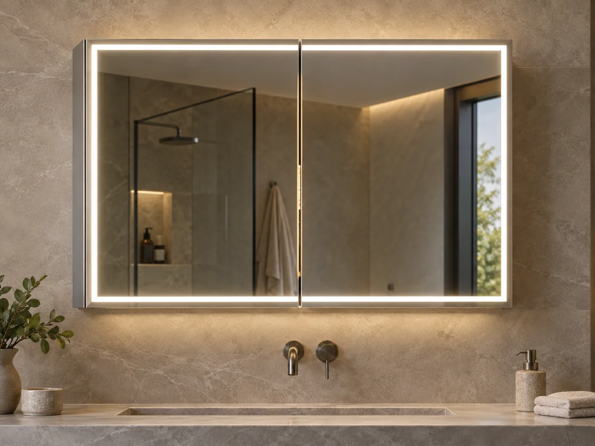
Integrated lighting coordinated with the mirror pattern and concealed cabinet body.
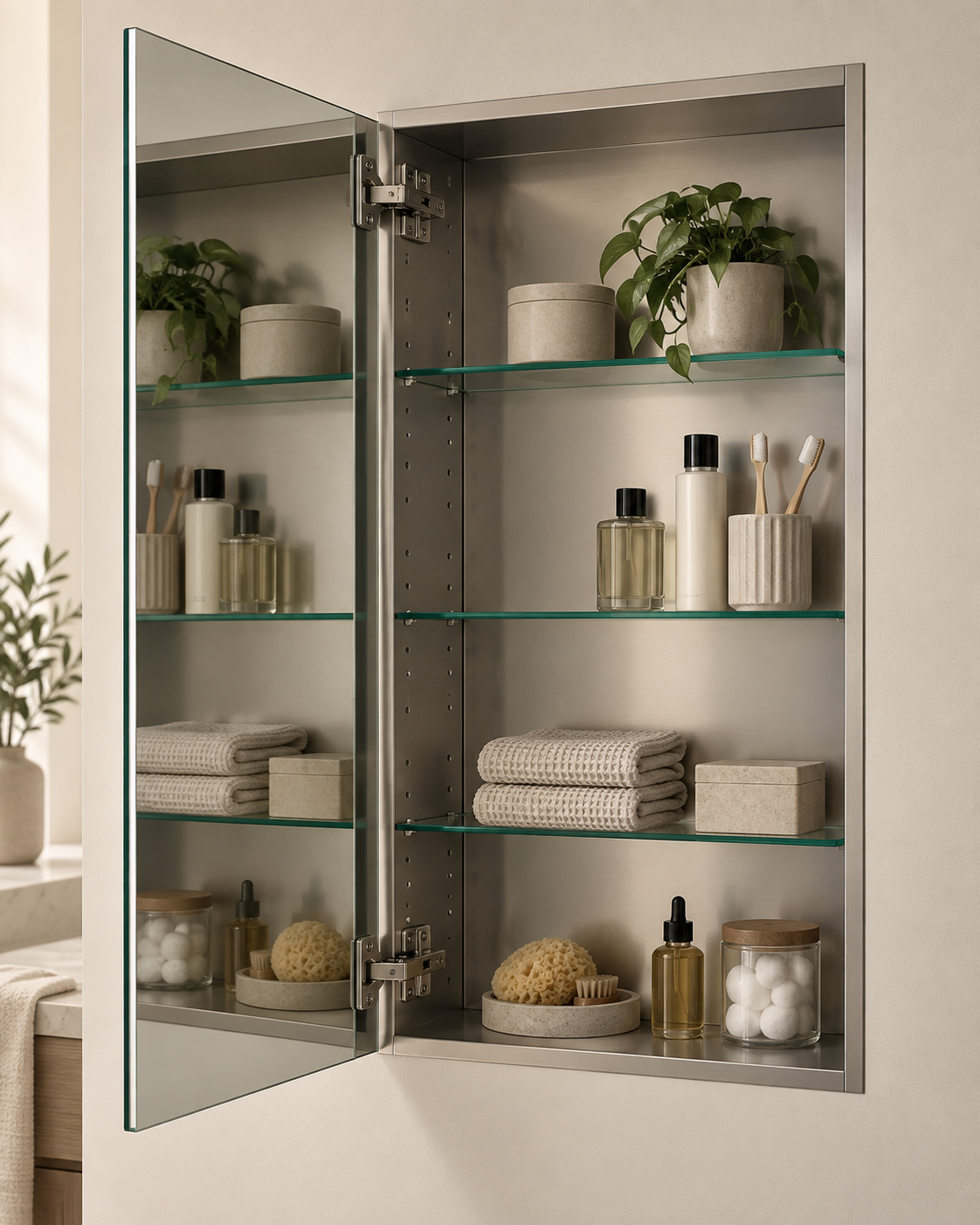
Review internal power and accessory requirements without losing usable storage.

Develop the visible face and hidden body around a measured opening or project elevation.
Size references above reflect common U.S. search and comparison language. They are not confirmed stock dimensions or rough-opening specifications; availability must be reviewed against the actual construction.
A function may be feasible without being standard. Review each option against cabinet size, internal space, wiring, controls and destination-market requirements.
| Option | What it changes | Information needed | Status language |
|---|---|---|---|
| Adjustable shelves | Usable storage zones, bottle height and shelf support positions. | Shelf count, spacing direction and interior depth. | CONFIGURATION REVIEW |
| Mirrored interior | Door-back reflection, cabinet-back treatment and internal finish. | Mirror coverage and edge/safety direction. | MODEL DEPENDENT |
| Soft-close hinges | Door movement, overlay, opening angle and internal interference. | Door size, weight, handing and nearby clearance. | HARDWARE REVIEW |
| Integrated LED | Mirror pattern, power entry, driver space, switching and service access. | Voltage, light direction, controls and market. | ELECTRICAL REVIEW |
| Defogger | Heated area, power load, mirror construction and control logic. | Requested coverage and switching method. | ELECTRICAL REVIEW |
| Outlet / USB | Internal component space, wiring, location and compliance scope. | Outlet type, voltage, position and destination. | MARKET REVIEW |
| Magnifying mirror | Internal clearance, attachment point and door/shelf interaction. | Magnification direction and preferred location. | LAYOUT REVIEW |
| Branding & packaging | Labels, manuals, carton artwork, protection and pack-out. | Program requirements, language and shipping route. | PROJECT REVIEW |
No option in this matrix should be treated as standard across every cabinet. Availability is confirmed only after the selected construction and order requirements are reviewed.
The cabinet may look similar from the front, while the documentation, packaging and approval process changes with the project.
Align cabinet size, lighting direction and opening conditions across repeated guest-room or public-area types.
Resolve wall opening, vanity proportion and service location before repetition across units.
Coordinate a recessed collection around size logic, features, labels, manuals and packaging.
Choose the closest project conditions. We will use them to review cavity fit, construction and electrical requirements.
A useful quotation connects the visible design to the hidden opening, cabinet body, internal hardware and installation route.
The approved drawing and order specification remain the reference. These checkpoints organize what should be confirmed for each project.
Inspection records, acceptance limits and test requirements are confirmed by model and order; this overview does not claim one universal report for every cabinet.
The approved drawing and reference—not a generic nominal size—become the basis for development and batch review.
Wall, size, quantity, market and product direction.
Opening, body, doors, interior and electrical scope.
Confirm appearance, fit, function and packing reference.
Build against the approved project specification.
Review agreed checkpoints and shipment preparation.
Most late changes happen when the visible mirror is selected before the hidden wall and installation information is resolved.
The mirror face, cabinet body and rough opening are different dimensions.
Tile, backing and trim affect depth, overlap and the final visible edge.
Studs, plumbing and wiring can change or eliminate the recessed route.
Side walls, vanity lights and adjacent doors can restrict handing or opening angle.
Lighting, outlets and defogging need space, power entry, controls and service planning.
Visible sides, trim, fixing and cable routes may differ between recessed and surface installation.
Send the overall width and height, cabinet-body depth, available wall-cavity depth and rough-opening dimensions if known. Final cutout and installation dimensions must be confirmed on the approved drawing.
No. The visible mirror or door, cabinet body and installation opening are related but different dimensions. The exact relationship depends on the selected construction and must be shown on its drawing.
Lighting, a demister, outlet or USB can be reviewed by model and destination market. Wiring entry, voltage, component locations and compliance requirements must be confirmed before quotation.
Some constructions can support both mounting directions, but side finish, trim, fixing and wiring can differ. Mounting capability must be confirmed for the selected model.
Confirm usable depth and identify studs, blocking, plumbing, wiring, insulation and other obstructions. Structural and electrical feasibility should be checked by the responsible local professionals.
They depend on size, construction, function, finish, electrical scope, packaging and quantity. OJMIRROR confirms them after reviewing the actual requirement.
A rough opening, wall section, overall size, room schedule or reference image is enough to begin a technical review.

Open WeChat and scan this QR code to contact our team.